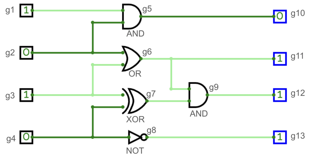
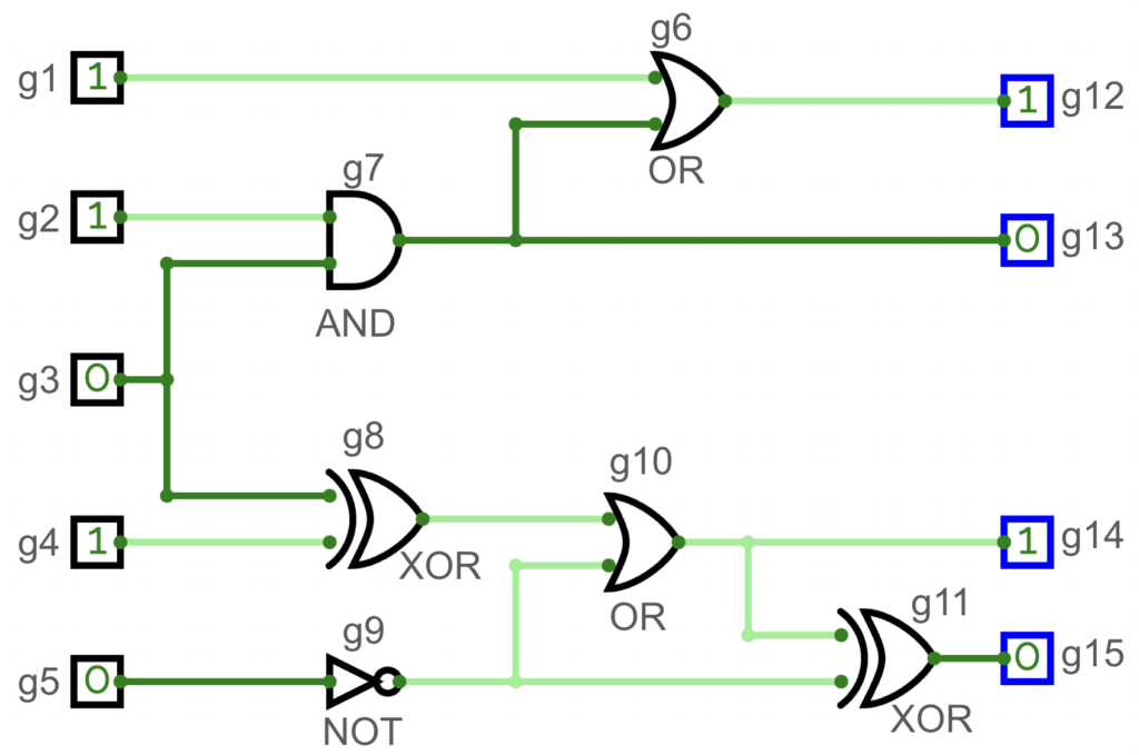
Please design a program to simulate a basic logic circuit system. This circuit system consists of several input ports, logic gates, and output ports. You need to simulate signal propagation through the circuit and gate operations to determine the values of all output ports and calculate the maximum delay time of the entire circuit.
The circuit includes the following components:
- Input Ports: You will receive several binary signals, each with a value of 0 or 1. These signals will serve as inputs to the circuit. There are a total of P input ports in the circuit, numbered from 1 to P.
- Logic Gates: There are four types of logic gates: "AND, OR, XOR, and NOT gates". These gates receive input signals and perform operations based on their functionality. There are a total of Q logic gates in the circuit, numbered from P+1 to P+Q. The operation rules for each type of logic gate are as follows:
- AND Gate: 接收兩個輸入,如果兩個輸入皆為 1,則輸出為 1;否則輸出為 0。
- OR Gate: Receives two inputs; if at least one input is 1, the output is 1; if both inputs are 0, the output is 0.
- XOR Gate: Receives two inputs; if the two inputs are different, the output is 1; if the two inputs are the same, the output is 0.
- NOT Gate: Receives only one input and reverses it. If the input is 1, the output is 0; if the input is 0, the output is 1.
- Output Ports: The final results will be output from these ports, with each port corresponding to the output value of certain gates. There are a total of R output ports in the circuit, numbered from P+Q+1 to P+Q+R.
To simulate this circuit system, you can create classes for input ports, gates, and output ports. Each gate should have inputs, an operation, and an output. Then, you can propagate signals through the circuit, computing the output values based on the inputs and gate operations. Finally, you can calculate the maximum delay time by tracing the longest path from input ports to output ports, considering the number of logic gates along that path.
Sample Inputs/Outputs
| Sample Input(s) | Sample Output(s) |
|---|---|
| The first line contains four integers: P, Q, R, and M. P (1 <= P <= 10^3) represents the number of input ports; Q (1 <= Q <= 5*10^4) represents the number of logic gates; R (1 <= R <= 10^3) represents the number of output ports; M represents the number of connections between components. The second line contains P integers v1, v2, ..., vP, representing the binary values (0 or 1) of input ports numbered from 1 to P. The third line contains Q integers t1, t2, ..., tQ, representing the types of logic gates (1 for AND, 2 for OR, 3 for XOR, 4 for NOT) numbered from P+1 to P+Q. The last M lines each contain two integers representing the starting and ending port numbers of the connections. Each input port and logic gate output will connect to at least 1 and at most 20 other logic gates and output ports, and there will be no loops in the logic gate circuit. | The first line outputs an integer representing the maximum delay time of the specified port, with the test data ensuring that the maximum delay does not exceed 100. The second line outputs R binary values (0 or 1), representing the output values of each output gate in ascending order of gate number. |
| 4 5 4 13 1 0 1 0 1 2 3 4 1 1 5 2 5 2 6 3 6 3 7 4 7 4 8 5 10 6 9 6 11 7 9 8 13 9 12 | 2 0 1 1 1 |
| 5 6 4 15 1 1 0 1 0 2 1 3 4 1 3 1 6 2 7 7 13 7 6 3 7 3 8 4 8 5 9 8 10 9 10 10 14 10 11 9 11 6 12 11 15 | 3 1 0 1 0 |
Sample Inputs/Outputs Explanations
Sample Input/Output 1

Sample Input/Output 2

Thought Process
You can use a struct to access the value of each endpoint/logic gate. After collecting all the data into the struct, you can use BFS (Breadth-First Search) to traverse the input endpoints. Then, store the start value of the endpoint's end value as the current number. After determining that the logic gate operation can be performed, you can store the computed value in the struct's output value variable. For the delay part, you only need to determine how many times BFS has been run and then subtract 1.
Sample Code-ZeroJudge M933: Logic Circuit
#include <iostream>
#include <vector>
using namespace std;

struct node
{
    vector<int>from;
    vector<int>to;
    int output = -1;
    int delay = 0;
    int gate = -1;
};

int delay = 0;
vector<node>vec;

void BFS(vector<int>start)
{
    if (start.size() == 0) return;
    delay++;
    vector<int>newStart;
    for (int i = 0; i<start.size(); i++)
    {
        node vv = vec[start[i]];
        for (int j = 0; j<vv.to.size(); j++)
        {
            int to = vv.to[j];
            vec[to].from.push_back(start[i]);
            if ((vec[to].gate == 4 && vec[to].from.size() == 1) || (vec[to].from.size() == 2))
            {
                newStart.push_back(to);
                node point = vec[to];
                int gate = vec[to].gate;
                if (gate == 1)
                {
                    if (vec[point.from[0]].output == 1 && vec[point.from[1]].output == 1)
                    {
                        vec[to].output = 1;
                    }
                    else vec[to].output = 0;
                }
                else if (gate == 2)
                {
                    if (vec[point.from[0]].output == 1 || vec[point.from[1]].output == 1)
                    {
                        vec[to].output = 1;
                    }
                    else vec[to].output = 0;
                }
                else if (gate == 3)
                {
                    if (vec[point.from[0]].output != vec[point.from[1]].output) vec[to].output = 1;
                    else vec[to].output = 0;
                }
                else
                {
                    if (vec[point.from[0]].output == 0) vec[to].output = 1;
                    else vec[to].output = 0;
                }
            }
        }
    }
    BFS(newStart);
}

int main() {
    cin.sync_with_stdio(0);
    cin.tie(0);
    int in, out, logic, line;
    cin >> in >> logic >> out >> line;
    vector<int>start;
    for (int i = 0; i<in+out+logic; i++)
    {
        node tmp;
        vec.push_back(tmp);
    }
    for (int i = 0; i<in; i++)
    {
        int tmp;
        cin >> tmp;
        vec[i].output = tmp;
        start.push_back(i);
    }
    for (int i = in; i<in+logic; i++)
    {
        int tmp;
        cin >> tmp;
        vec[i].gate = tmp;
    }
    for (int i = 0; i<line; i++)
    {
        int a, b;
        cin >> a >> b;
        vec[a-1].to.push_back(b-1);
    }
    BFS(start);
    cout << delay-1 << endl;
    for (int i = in+logic; i<in+logic+out; i++)
    {
        cout << vec[vec[i].from[0]].output << " ";
    }
    cout << "\n";
}

//ZeroJudge M933
//Dr. SeanXD